RR Racing Brake Systems Design

Our brake kits are engineered from the best-in-class components, carefully designed, selected, and/or manufactured by us right here in the United States to the highest quality standards. Our goal is to meet and exceed all quality, performance, aesthetic characteristics of top brands such as Brembo and AP Racing at an affordable price. All of our braking systems are track tested in very demanding conditions (please refer to our News page for latest track testing articles).

Big Brake System Components:

Rotors
Calipers
Brake Pads
Shims
Brake Lines
Mounting Brackets

Rotors

RR Racing is using DBA two-piece floating rotors for all our GT86 (FRS/BRZ) Stage 4 front BBKs.   We have found out that the DBA two-piece STi compatible rotors are the best rotors for track applications.

For our Lexus and Porsche customers, we offer the racing grade rotors available — the GiroDisc racing rotors.  These rotors have been proven by many race teams again and again on the track.  They can also be used for road applications.

Calipers

After testing a variety of calipers for our high-end brake kits, we concluded that Wilwood calipers offer the best performance at a great value. RR Racing Wilwood calipers were carefully selected and extensively tested with our braking systems. We utilize several four and six piston calipers with varying sizes ranging from FNSL6R in our Stage I kit and FSL6R in our high end and Competition kits. We also use Aero6 for our large disc Competition kits (e.g., ISX competition brake kit).

The Wilwood Forged Superlight 6R series is the benchmark in street and track applications. It also enjoys prominence in a variety of road-race, rally and sport driving. The new FSL6R model series is the latest innovation to this Superlite family of calipers. It has been redesigned with internal fluid ports that eliminate the external fluid cross-over tubes. The transfer tube has been replaced with two additional bleed screw assemblies which allow differential bore models to have a left hand and right hand orientation, but no leading or trailing configuration is required.

The Forged Narrow Superlite 6R (FNSL6R) is Wilwood’s newest version for the venerable Superlite caliper series adds the versatility and convenience of radial mounting to this widely popular caliper group. Radial mounting simplifies adaptation and provides two planes of adjustment for accurate alignment over the disc. These calipers integrate “Big Brake” style with Wilwood’s latest technology to generate big stopping power in extreme environments over a broad range of vehicle applications.

The new Aero6 forged six piston caliper delivers heavy duty stopping power for the road or track. The caliper incorporates race technology into a body design with widespread adaptability. Radial mounting, multiple options for piston volume, and large rotor diameter (we use it in our 14 inch kits) give this caliper the versatility necessary to suit all types of heavy weight braking requirements.

In most of our kits we offer Wilwood calipers in black or red powder coated colors. Wilwood calipers offer both superior performance and great aesthetic looks. Our competition kits feature black anodized calipers to withstand the extreme temperature conditions associated with track use.

Update September 2015: We now offer the calipers on variety of standard colors and any custom colors that could be selected from www.g2usa.com. Calipers are painted using a two component high temperature paint. We found this paint very durable even after repeated track uses (although we recommend the anodized version for heavy track/racing applications). Painted calipers get a great looking RR Racing logo, or our customers can specify no logo for applying their favorite car logo (as shown on the GS350 application photo below).

Offering custom calipers colors is a unique feature in the market today, and we feel it provides an important service to our customers looking for a unique look. We engineer our brake systems for best quality, variety of flexible options at a great price!


Brake Pads

We offer Wilwoods BP10 through BP40 pads as well as Carbotech 1521pads as an option for some of our high-end braking systems. Temperature range and overall friction value are the primary considerations for pad selection. The pads must be capable of maintaining the proper amount of friction for stopping power within the temperatures that will be realized during demanding road applications or on the track. Then, overall wear rate must be considered. For most asphalt and road race applications, compounds in the high temperature ranges over 1000°F range are usually necessary. Dirt track, drag race, and street performance applications usually operate at temperatures between 500° and 1000°F. The best indicator for pad selection will always be on track performance – this is why we test our brake systems on the track.

Carbotech 1521 pads are the best pads for low dust and low noise applications.  We do not recommend them for track applications.

We also like the Winmax brake pads. Winmax offers a variety of pad options starting at high performance street use through tracking and racing. We like Winmax pads for their temperature and friction characteristics. We feel they fit well with certain OEM and RR Racing brake systems.
Please refer to our Pad Guide for more technical information about our brake pad options: Brake Pad Selection Guide


Titanium Shims

For selected racing applications we offer our own designed and manufactured Titanium Pad Shims. In race applications, it is common to use titanium backing plates to reduce heat transfer between the brake pad to the caliper pistons. Titanium is superior to common steel backing plates due to its lower thermal conductivity. It acts as an insulator to prevent heat transfer to the caliper pistons and brake fluid.

Please note that these shims are only available for Lexus ISF and RCF/GSF calipers.


Brake Lines

We exclusively use Goodridge USA stainless steel brake lines. High speed heavy braking puts great strains on competition hydraulic systems, where failure can be disastrous. Goodridge stainless steel hose strongly resists expansion under high pressure and temperature, provides consistent brake pedal pressure giving firmer and more efficient operation without that spongy feeling. These brake line systems offer protection against abrasion and fire. Its microbore construction can give increased line pressure and more responsive and sensitive brake feel.


Mounting Brackets

RR racing designs and manufactures caliper mounting brackets needed for each of our big brake kits. Mounting brackets are made of high strength aircraft aluminum for both durability and light weight. We machine our brackets using the latest CNC milling machines to high quality standards right here in United States. As with all our aluminum components, we black anodize our brackets to give them superior strength and corrosion resistance.

For more information about our brake systems products, please visit our on-line catalog for your model.

Brake Pad Selection

Selecting the right brake pad for your application can be a difficult task. Going with a street pad at the track or fast canyon road may ruin your day. Conversely, a dedicated race pad may overpower your tires and result in premature triggering of the ABS system, thereby reducing the overall performance of your braking system. At RR-Racing, we have experimented with most of the compounds detailed in the charts below. We can order ANY pad compound available for your application, but based on our experience, we keep the following compounds in stock, as we have found they will meet 90% of our customer’s needs. If you have any questions please do not hesitate to call or email us.

Pad Compound Co. of Friction Temp. Recommendations/Notes
Wilwood BP10 0.40-0.45 Up to 800F Excellent pad for street performance applications, but not recommended for aggressive track day use. Available for our big brake kits.
Wilwood BP20 0.40-0.53 Up to 1100F Our pad recommendation for someone looking for a dual purpose street & track pad. This pad is not noisy, normal dust levels, and performs well at HDPE track days. Available for our big brake kits.
Wilwood BP30 0.60-0.63 Up to 1300F Due to the extremely high coefficient of friction, we recommend this pad for track day use only with semi-slick or full race slicks. This pad is easy on rotors, and works very well when cold, but we have found that it is simply too aggressive for street tires. Available for our big brake kits.
Winmax W1 0.29-0.32 Up to 842F Non steel material pad, low dust, street use only.
Winmax W2 0.32-0.35 Up to 932F Ceramic based pad, low dust, high performance street use, light track.
Winmax W3 0.34-0.37 Up to 1112F All purpose street/track pad. Increased dust/noise compared to W2’s
Winmax W4 0.37-0.40 Up to 1200F Track pad that can be used on the street.
Winmax W5 0.40-0.43 Up to 1382F Primarily a dedicated track pad, high metal pad not recommended for street use.
Endless MX72 0.37-0.47 Up to 1292F Great pad for both street and track use.
Hawk HPS 5.0


0.40-0.53 Up to 750F Great overall street performance pad, low noise and dust.   This pad is available for OEM applications only.
Hawk HP-Plus 0.50-0.56 Up to 900F HP-Plus is our recommended dual use pad for street performance, autocross, and track days.   This pad has a very high friction coefficient that is very consistent across the temperature range.   This pad is available for OEM applications and our big brake kits.


Figure 1a: Wilwood street compound friction coefficient vs. temperature chart.


Figure 1b: Wilwood race compound friction coefficient vs. temperature chart.


Figure 2: Windmax W1/W2 friction coefficient vs. temperature chart


Figure 3: Windmax W3 friction coefficient vs. temperature chart


Figure 4: Windmax W4 friction coefficient vs. temperature chart


Figure 5: Windmax W5 friction coefficient vs. temperature chart


Figure 6: Hawk Performance friction coefficient vs. temperature chart.


MX72_charts

Figure 7: Endless MX72 characteristics chart

Suspension Design

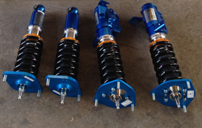
Our suspension kits were engineered in cooperation with Penske Shocks and
manufactured by Penske and us right here in the United States to the highest quality standards. All of our suspension products were track tested in very demanding conditions (please refer to our News page for latest track testing articles).

After introducing our Penske coilover suspension for the IS-F and RCF, many of our customers were amazed at the improved handling and at the same time the comfort of this suspension. Many expect sport suspension to be harsher and uncomfortable, but they were surprised that our suspension is as comfortable (or some say, even more comfortable) than the OEM suspension. This page explains from a technical perspective our suspension performance and design principles that make this suspension the best suspension available for these cars. We also explain the major differences between our suspension tuning philosophy and design versus other suspension systems offered for the Lexus RCF, ISF, IS, and RC models (i.e. KW-V3, Ohlins R&T, and RSR coilovers).

Please note that you can buy our suspension products on our on-line store here:
Lexus IS-F Suspension Products
Lexus RC F Suspension Products

The following topics are covered here:

1. Spring Rate Selection – Advantage of Using High Spring Rates.
2. True Rear Coilover Conversion for the 3rd generation Lexus IS/RC platform.
3. Advantages of Using Articulating Upper Spherical Bearing Top Mounts.
4. Advantages of Using Dual Springs vs. “Preloaded” Springs.
5. Penske 7500 Series shocks vs Ohlins R&T, KW V3, and other shocks — this is why they are superior.
6. Taking advantage of the Penske 7500 double independent compression & rebound adjustment to fine tune your handling.

1. Spring Rate Selection

Let’s start with spring rate choices. We utilize spring rates that are significantly higher than our competition. Higher spring rates allow for:

  • Better weight transfer dynamics,
  • Reduced body roll,
  • Reduced understeer as you approach the limit, and
  • Linear and more predictable handling behavior.


Figure 1 below is a good *estimate* of what happens in the IS/GS front suspension during cornering. We illustrate the amount of force that is required to compress the suspension (bump travel) for a sample 900lb spring (16kg), 560lb spring (10kg), and the bump stop. Looking at the curves, it is clear that the bump stop behaves very different compared to a spring – spring force increases linearly with deflection, while bump stops behave linearly at first, but as we approach the limit of travel, force required to compress the bump stop increases exponentially. The two vertical green dashed lines indicate how much compression of the front suspension we can expect under about 0.9g of cornering force and 750lbs of lateral weight transfer for the two spring choices.

(Note: This is just a good estimate of the amount of increase in loading and displacement you would see on an RCF under about 0.9g cornering force, the precise calculation depends on knowing the exact weight of the car, front/rear weight distribution, center of gravity height, track width, motion ratio of the suspension, and shock inclination angle).


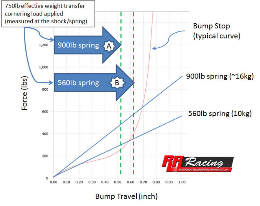
Figure 1: Graphical representation of spring and bump stop curves

If we take the spring force/deflection curve and combine it with the bump stop force/deflection curve, we get two curves for each spring/bump stop combination (curves “a” and “b”), as shown in Figure 2.

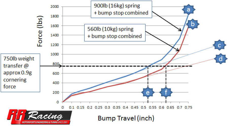
Figure 2: Comparison of force/bump curves for 900lb vs. 560lb springs

The following are important differences in the behavior of the softer vs. stiffer suspension derived from the graphical illustration above (and from actual track testing):
(1) When the lateral weight transfer of 750lbs is applied, the suspension with the stiffer springs (curve “a”) behaves completely linearly as the combined spring/bump stop curve closely follows a linear behavior (line “c”). The increase in loading on the wheels is more predictable and the driver has a better feel for the behavior of the car. Even as more than 750lbs load is applied to the spring/bump combo, we only see a minor deviation from linear spring loading. In the more softly spring suspension, you can see that after about 0.55″ of travel (see Figure 1), the force of the bump stops is starting to ramp up very quickly (beginning an exponential rather than linear ramp up). Any further increase in weight transfer and corning force results in non-linear bump travel and rapid non-linear increase in the effective spring rate (where the bump stop effectively takes over from the spring). This type of behavior typically induces severe at-the-limit understeer.
(2) Comparing points “e” and “f” under similar weight transfer, you can see that the more softly sprung car will roll more (more bump travel for the applied load). The only way to reduce roll without using stiffer springs is by either increasing the bump stop stiffness, or using a larger roll bar. Unfortunately, increasing the bump stop stiffness will only make the situation described in above worse (more non-linear behavior). Likewise, increasing roll bar stiffness has negative consequences as well, such as reducing the independent movement of the suspension and inducing inside wheel lift.

Ok, so some may ask, “doesn’t increasing the spring rate so much result in a harsh ride?”

No, not necessarily. This is where careful consideration of wheel rates and spring frequencies come into play. But the real advantage we have in designing a suspension that is both track-worthy and comfortable is the quality of the shocks we use, our ability to tune shock valving, and the incredible resource we have with our close interaction with Penske race engineers.

When you are traveling on a bumpy road, the shock is actually playing a more important role than the spring in terms of what you feel. Bumps on the road force the shock to travel at a high speed, due to the sudden impact of hitting something. Penske has done an amazing job at assisting us with shock valving. We achieved what is known as “digressive” rate curve, where the shock valving is set relatively soft at high shock travel speeds, making the ride over bumps very comfortable. Digressive valving also means that the shock valving at low shock speeds (low shock speeds occur when you change the direction of the car) is relatively hard, resulting in handling behavior that feels very responsive. There are other advantages to using the Penske 7500 shocks which we outline later in Part 5.

That said, some may ask, “Well, if increasing spring rates so much is so good, why doesn’t ever aftermarket coilover manufacturer do this?”

The higher you go with spring rates, the more energy the shock must absorb. More energy equals more heat and more stress. So now you need to use better materials to make the shock, and machine everything to higher tolerances and higher quality control procedures. All these things are what make Penske Shocks more expensive (not to mention their proprietary shock pistons designs and internals which are the same as found on their uber-expensive full race shocks). Utilizing higher spring rates on a lower quality shock results in reduced shock life/durability and inability to control the rebound energy of the suspension, thereby resulting in a bouncy ride.

There are other things that make our suspension better (other than the Penske shocks), such as our “True Rear Coilover” conversion, and the fact that we use an articulating upper spring perch to maintain co-axial spring loading of the shock absorber.

2. The True Rear Coilover Conversion

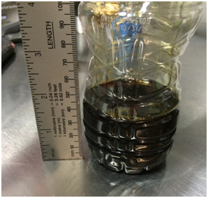
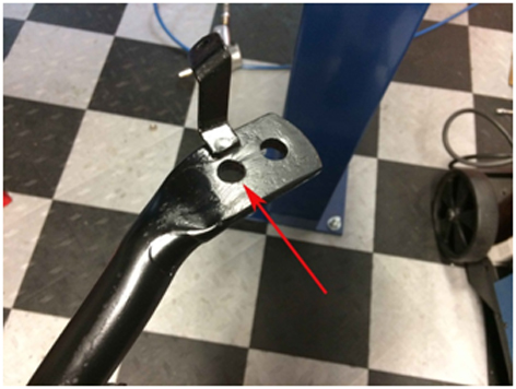
When Lexus re-designed the IS/GS/RC platform (3rd generation) they changed the rear suspension design from a rear coilover shock, to a divorced spring setup as shown in Figure 3 below. In a divorced spring setup, the spring no longer sits on the shock absorber, rather it is wedged between the lower control arm and the floor pan of the rear trunk. Manufacturers most likely do this out of space and noise considerations, but certainly not for performance!


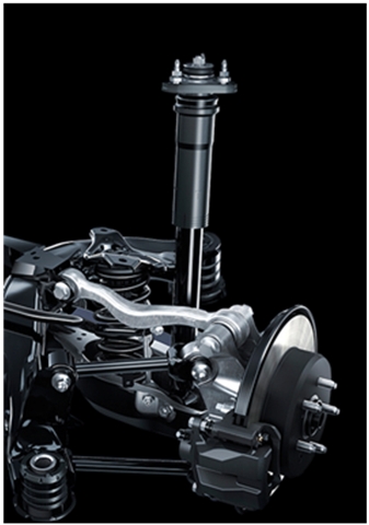
Figure 3: Stock RCF Rear Suspension with “Divorced” Rear Springs

The main problem with a divorced spring rear suspension is the inability to adequately increase spring rates in the rear due to the reduced motion ratio of the inboard spring location. High spring rates are essential in taming the weight of a 3900lb Lexus RCF. In Figure 4 we illustrate the motion ratios of the spring when it is placed at the “divorced” inboard location, versus at the shock absorber (“the True Rear Coilover”).


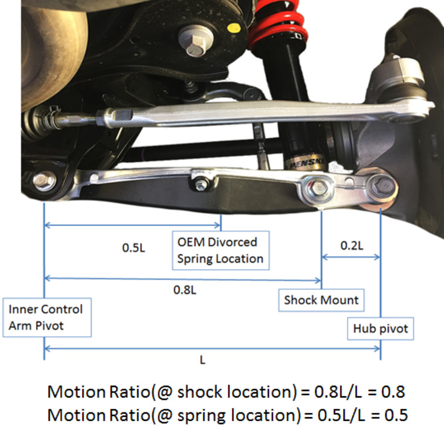
Figure 4: Illustration of the Motion Ratios of the RCF Rear Suspension

Given our road and track testing on the RCF with our true rear coilovers, we found that a good spring rate choice for overall comfort and road/track performance was about 14kg at the rear shock absorber. If we plug into our motion ratio equation (see Figure 4), that would require a 22kg spring placed at the divorced spring location! To put that into perspective, one of our competitors makes an RCF “coilover” that utilizes 14kg rear divorced springs. Plugging into our motion ratio equation, we see that a 14kg divorced rear spring is equivalent to only 8.75kg at the shock absorber! That is nearly 40% softer then what we use on our coilover kit. While a 14kg divorced spring is stiffer than stock, it is inadequate and will result in a lowered suspension that relies on bump stops to reduce body roll. As we learned in Part 1, keeping the suspension off the bump stops maintains linear, predictable, and neutral handling behavior at the limit of tire adhesion.

So why can’t you just use a 22kg spring at the divorced spring location?

The problem becomes that in order to fit a spring with a rate that is so much higher than the stock spring, you have to make the spring much shorter in order to achieve lowering of the rear suspension. Problem is, when you shorten the springs, you also shorten the rear “droop” travel. Sufficient droop travel is essential in order to maintain stability over large bumps. Also, cars with insufficient droop travel tend to lift inside wheels during cornering, something that is not good for traction or stability. The other problem with shorter and stiffer springs is the high mismatch angle between the lower control arm and the spring, resulting in excessive bowing of the spring, and non-linear spring behavior. Spring bowing is much more problematic in very stiff springs compared to soft OEM springs.

3. Advantage of Using Articulating Upper Spherical Bearing Top-mounts and Lower Mounts.


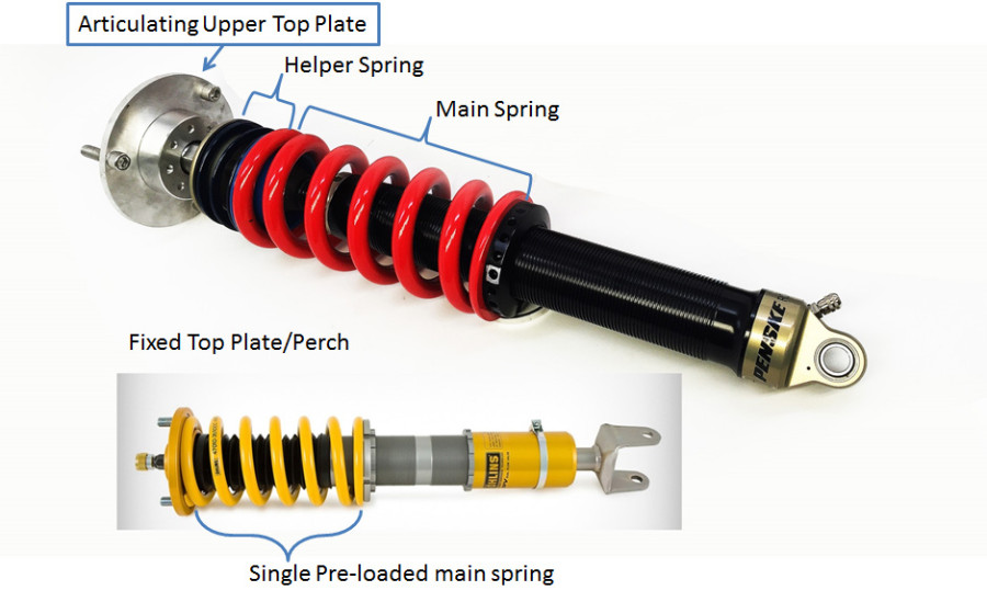
Figure 5: Articulating vs. fixed top-plates

Another advantage of the RRRacing/Penske Coilover System is our top-plate design, which allows the spring to compress co-axially with respect to the shock absorber by utilizing an articulating top-plate to accommodate changes in the shock angle as the suspension moves. Making sure that the spring does not bow is essential in terms of maintaining spring rate linearity, shock absorber response, and long-term durability of the shock. Figure 5 above shows our articulating top-plates versus a competitor’s fixed upper top plates.

At stock ride height the upper top-plate is perpendicular to the shock motion axis. But as we lower the car, or as the suspension moves during cornering or bumps, a misalignment angle develops between the shock axis, and the upper top-plate. Figure 6 illustrates what happens when a spring bows due to angular displacement of the shock absorber when upper top-plates are fixed. If we make a quick approximation of the amount of lateral loading experienced by the shock at full compression with a simple vector analysis, we can see that the shock can easily see lateral loads of up to 47lbs. Lateral loading restricts the movement of the shock piston and results in reduced sensitivity, and increased wear/deterioration of shock performance over time.


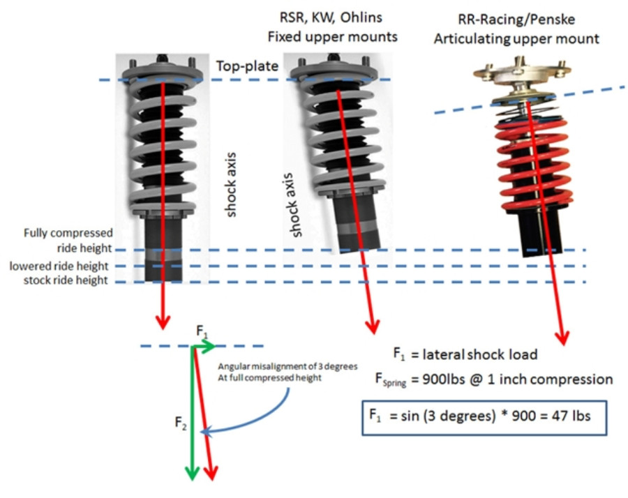
Figure 6: Approximate calculation of lateral shock load component induced by spring bow & misalignment
(Note: In reality, a spring axis of force is not perfectly co-axial even when the upper and lower perches are aligned).

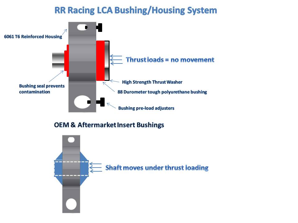
Another contribution to lateral shock loading is the rubber mounted lower mount bushing used by our competitors. While we offer polyurethane lower shock mounts, we recommend that our customers retain the Aurora spherical bearings that are standard with our coilover kits. For most performance minded enthusiasts, the slight increase in noise over rough roads is easily worth the added performance benefit of the spherical bearing lower shock mounts.

4. Advantage of Using Dual Springs versus “Pre-loaded” Springs.

When designing height adjustable coilovers, there are two options: (1) Single preloaded spring with height adjustable lower collar, and what we use (2) Dual main & helper springs (see Figure 5).

Pre-loaded coilovers are typically used for mass-market street applications because they allow use of a single shock body over a wide product range (since the shock body can be lengthened or shortened per the application rather than making many different length shocks). The other advantage of the pre-loaded setup for mass-market application is that it only requires 1 spring per shock, thereby saving cost of helper springs and spring couplers.

The problem with pre-loaded coilovers is that as you increase the spring rates for reasons we outlined in Part 1, you reduce the suspension’s “droop” travel. Droop travel is defined as the distance that your wheel drops when your car is lifted. OEM suspension springs are typically pre-loaded, but they are very soft, so they maintain sufficient droop travel.

Let’s take an example of an OEM suspension with 450lb spring versus an aftermarket high performance suspension with 900lb springs. If the sprung corner weight of the car is 900lbs, then we would expect that the OEM spring will compress 2 inches under the weight of the car, while the high performance suspension will compress about 1 inch. Consequently, the aftermarket suspension will have about ½ the droop travel of the OEM suspension. In reality, the suspension with 900lb pre-loaded springs will have less than 1” droop travel (measured at the shock) because some travel is taken up by the pre-load compression of the spring.

All our coilovers use helper springs in addition to main springs. The helper spring has a relatively low spring rate, about 50-100lbs and is designed to allow the main spring to completely de-compress when the wheel is at full droop, without the main spring coming loose. In most cases, using helper springs increases droop about 1-1.5” over a pre-loaded single spring setup.

Sufficient droop travel is critical to maintain stability and wheel contact with the road over large road bumps and track curbing. In some cases droop is so limited that wheels will actually lift under hard cornering as shown in Figure 6 below.


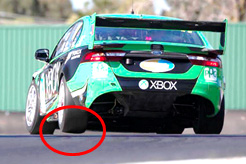
Figure 7: Insufficient droop travel results in wheel lift during hard cornering

The bottom line is that a road car needs ample droop travel to maintain traction and stability over uneven roads, more than most aftermarket coilovers allow, but maybe not as much as the rally car in Figure 7!


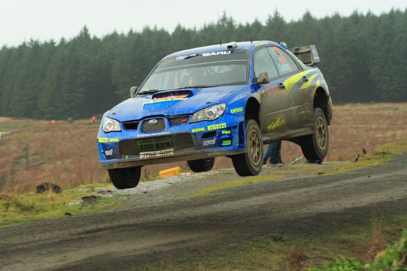
Figure 8: Example of “Extreme” droop travel in a WRC rally car!

5. The Penske 7500 Series Shock vs. the Competition

Unfortunately, in recent years, the coilover market has become saturated with cheap low cost imported coilovers. These coilovers have lots of features on paper, but ultimately do not come close to the performance achieved with the Penske 7500 series shock.

To try to counteract the cheap coilover trend, certain Swedish, Japanese, and German companies market premium “road and track” coilovers. Unfortunately, their street offerings are actually designed around lower cost shocks which are colored the same as their uber-expensive racing products, but ultimately lack the standout design features that give them their racing reputation!

The way we view it, it’s kind of like a “bait and switch” tactic…. but if you are in the market for a $3000 coilover, shouldn’t you get the real thing?

So what makes Penske 7500 series shocks the “real thing?”:

  • The 7500 shock internals, from their piston design to their head valve are the same as used in their high end 8760 and 8780 championship winning racing products. The 7500 series shocks, while designed as a road & track offering, are actually raced in many forms of professional motorsports.
  • Many professional racing teams can get imported “race” shocks for free, but they choose to buy Penskes.
  • Penske shocks are 100% hand built and manufactured in the USA. Penske 7500 Series shocks are built in the same facility, and by the same techs who build IndyCAR, NASCAR, and all their race product – no “bait and switch” Psst… those “Swedish” road and track shocks are actually made in Thailand.
  • Every Penske 7500 series shock is dyno tested after assembly. This ensures that every shock behaves precisely per the specification sheet – no mass production here.
  • Durability and spares support: In the event of an accident or damage to your shock, the Penske Racing Shocks Headquarters in Reading, PA stocks ALL the spare parts necessary to rebuild and repair your shocks. With that kind of support, your shocks will outlast your car!
  • Penske 7500DA shocks offer independent compression and rebound adjustment. This feature is critical to perfectly dialing in your car for the track, or for street comfort.
  • At RR-Racing we spec out our 7500DA shocks to custom lengths. Our completion uses a “stock” length shock with a threaded lower shock mount. By maximizing the lengths of our shocks, we increase the oil volume for improved durability and performance over a large temperature range.
  • Penske shocks utilize a dual flow valve similar to other high end monotube shocks, but in addition to that, Penske shocks feature a unique head valve (see Figure 8) allows for reduced internal gas pressure. In a conventional monotube gas pressurized shock, high gas pressure is used in order to reduce aeration of the shock fluid, also known as “cavitation.” However, while gas pressure is beneficial in reducing cavitation, excess pressure can reduce the response time and sensitivity of the shock. The Penske 7500 shock is designed with a head valve and effectively acts as an inline dual reservoir shock. The head valve and inline reservoir design allow Penske engineers to use lower gas pressures for increased sensitivity, reduced internal friction, improved damping performance over a wider temperature range, improved durability, and reduced weight.


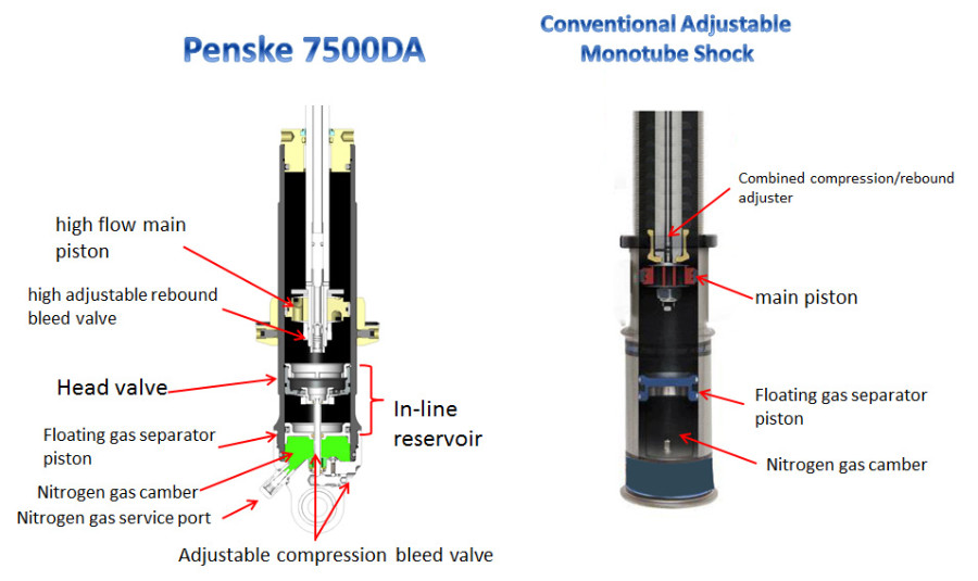
Figure 9: Conventional monotube shock cutaway versus the Penske 7500 dual internal reservoir shock

6. Adjusting your Penske 7500DA shocks

Track Tuning for Road Racing

Compression Adjuster:
This adjuster is typically used when looking to improve the car over bumps. If your vehicle is hitting a certain bump that is causing the vehicle to “unload” the tire, simply soften the compression adjustment. This will allow the shock to absorb the bump, there keeping the vehicle more stable and making the car more controllable.

You can also use this adjuster to help in controlling the “platform” of the car, or the body roll. Example‐ If you are entering a corner and under braking the front of the car is diving to quickly or the weight being transferred from the back to the front is too much, simply close the compression adjuster on the front to slow that weight transfer down.

Rebound Adjuster:
The rebound adjuster is a great tool for tuning body roll. This is a much more driver sensitive adjustment than the compression. If you want to slow the pitch of your car from the back to the front, simply close the rebound off, this will slow the weight transfer.

When you are accelerating off a corner, getting weight transfer to the rear tires is very important for grip or “forward bite” as its referred to sometime. By softening the front rebound, this will allow for quicker weight transfer to the rear tires, resulting is better rear grip. Be careful though, by allowing to much weight transfer to the rear, you may cause a loss of front grip, resulting in an “under steer” or “tight” condition.

Important!! You can over adjust. Always have a baseline to go back to!!!

Track Tuning for Drag Racing

Normal adjustment steps for Drag Racing:
Compression: Adjust 5 clicks at a time.
Rebound: Adjust ¼ turn at time.

To Increase Rear Traction:
Soften rear compression and stiffen rear rebound. Soften front rebound. This will allow your car to “squat” transferring traction to the rear wheels!

Project Honda S2000


When we originally drove this car we were impressed with the balance, handling, and intimate cabin, but were underwhelmed with the power. Although the Honda F20C engine absolutely screams to 9000rpm, the fact of the matter is that by today’s standards, the S2000 simply does not have enough muscle to wow us. Some purists say that S2000’s should remain normally aspirated. NONSENSE…. They obviously never drove an S2000 with forced induction!

Our goal for this car was not to build a 500+whp dyno queen, rather we focused on building an “Ultimate Response” car with gobs of torque at low RPMs, instant spool, and sufficient high end punch. Rather than going with a Garrett GT3076 setup which is common among turbo S2000’s, we decided to try the new Borg Warner EFR7064. The EFR is a smaller turbo, and on paper does not have quite the flow capacity to match the S2000 engine at 9000rpm, but we were able to achieve 420hp at the wheels (on a Dynapak dyno) with a conservative pump gas tune utilizing Hondata Flashpro.

Instant response and torque make this car a blast to drive. This setup makes significant torque from 3500rpm. That means that this engine has a useful power band of 3500-9000rpm, which is simply insane. We like to joke that with this setup, you can easily outrun a stock S2000 without ever revving past 5000rpm!

One of the keys to achieving fast spool is our turbo manifold, constructed from schedule 40 stainless piping. The short runners ensure fast spool and maximum heat retention. Another key aspect to achieving fast spool is the lightweight Titanium Aluminide turbine used in the EFR7064 turbo.


So there you have it, the recipe for an exhilarating ride in an S2000 is a mid-size turbo, with fast spool characteristics and 420whp for top end punch. We completed the build by tidying up the engine bay and enclosing the air filter in a custom box in order to reduce air intake temperatures.


And one last parting shot (you will need some sticky tires with this kind of power & torque;-))

Project BRZ/FR-S


Back in 2013, a good customer of ours came to us looking to build the ultimate canyon racer. The stock BRZ/FRS is a great platform, but in stock form it simply lacks power and grip. Starting in the power department, we decided to build our own custom turbo kit. The basis of the kit would be the new Borg Warner EFR 6758 turbo which features ball bearings, billet compressor, and a lightweight Titanium Aluminide turbine wheel for immediate response and fast spool. Our goal was no more that 400hp, but the car had to have instant response with no turbo lag above 4000rpm. We set about fabricating the turbo manifold out of schedule 10 stainless steel.


Once the manifold and downpipe were complete, we completed the intercooler installation. We chose a relatively small intercooler because we did not want to cut all the airflow to the radiator. The FA20 engine runs very hot, and closing off the airdam with a large intercooler significantly reduces the cooling efficiency of the radiator. Additionally, because we are running water/methanol injection, intercooler efficiency is less critical. One of the most important aspects of installing an intercooler or any other type of cooler is getting a sufficient pressure differential across the core. By ducting the intercooler, we are able to significantly improve the efficiency of a relatively small intercooler. By using a top mount inlet and outlet, we were able to significantly reduce the volume of piping and thereby improve the transient response of the turbo.


And there you have it… the completed turbo setup. We were very impressed with this engine’s response to forced induction. The FA20 just wants to make tons of power, and with the new combustion chamber design combined with direct injection, is extremely resistant to detonation, especially compared to other Subaru engines such as the EJ20 and EJ25. That’s the good part about the FA20. The bad part is that the connecting rods are extremely weak (they are cast, not forged), and we highly recommend that anyone thinking of installing a turbo or SC on this car FIRST invest in an engine build. This is not something you want to put off, as a connecting rod failure will mean throwing the entire engine out, and will be much more costly than building it right the first time. For added reliability, we ran the Element Tuning Hydra EMS stand-alone engine management coupled with Aquamist water/methanol injection.


Of course, we did not leave the rest of the car unattended. The addition of 17×9 Enkei RPF1’s wrapped with Hankook 255/35R17 RS3’s gave this GT86 enormous levels of grip. We would also like to thank Cusco Japan for their assistance and sponsorship of this car. Cusco provided their Zero A suspension package coupled with electronic remote adjusters, strut brace with integral brake master cylinder brace, catch can, steering bushings, transmission bushings, rear differential support and bushings, as well as front and rear roll bars. The capabilities of this car, when well modded, are truly remarkable!


And last, but certainly not least we upgraded the brakes to provide endless fade free performance. Since this was not built to be a pure track car, we went with our “Stage II” 13″ solid rotor upgrade kit featuring 6 piston forged Wilwood race calipers and Goodridge USA stainless steel brake lines all around. Our Stage II kit is designed specifically to retain the proper brake bias, reduce unsprung weight, and provide massive stopping power.

RR Racing Stage 4 BBK for FRS/BRZ


Project IS-F

RR-Racing-ISF-lowres

Welcome to our Lexus IS-F tech project. Here we will summarize our development of the IS-F, taking it from a great executive sports sedan, and transforming it into a Porsche and BMW fighting weekend track warrior. Sometimes we are asked why we chose the Lexus IS-F. Well, we love the car, it is an awesome chassis, rare, and has an amazing v8. We were also amazed at the lack of meaningful performance parts for this car, but we are changing that, so tune back here often to follow our progress!

Part I: Taking it to the track
The photo at the top of this blog was updated in September 2015 and shows our new aero package for the IS-F. After increasing the track speeds, we felt that it needs a large wing in the back for better traction and handling. We chose an APR wing and adopted it for the IS-F. This wing produces about 800 pounds of force at 130 mph. The wing made a big difference in handling – just see some of the latest videos from our track sessions on our News page.
A front splitter was also added. The splitter was strictly for the track made of composite plywood 😉 Don’t laugh this is what many race teams use.

One of our initial goals was to improve braking performance by engineering a fully floating 2 piece front brake rotor. Working in conjunction with our rotor supplier, Coleman Racing, we utilized slightly thicker 360mm by 32mm rotors (OEM rotors are 30mm thick). Compared to stock, these rotors have more thermal mass where it counts, at the brake friction surface. The rotors also feature directional cooling vanes and optional slotting or drilled configurations, dynamic balancing, stress relief heat treatment, and zinc chromate plating to inhibit corrosion. Most importantly, we utilized a fully floating 2 piece design that saves approximately 6lbs of rotating mass per rotor, and allows for thermal expansion and contraction of the rotor under extreme track conditions. So bottom line is, these rotors are tough, light, and will take all the abuse you can throw at them.

In 2018 we later replaced these rotors with an even better design from Girodisc.  Girodisc made a custom ISF rotor for us per our specification utilizing their renown metallurgy use by many Porsche race teams.  

Even before arriving at the track, we became aware of a PCV (positive crankcase ventilation) issue with the ISF. The ISF v8 generates a significant amount of oil and crankcase vapors that get sucked into the intake manifold. As illustrated in the picture below, when simply disconnecting the PCV inlet hose at the intake manifold shows that the pipe is literally wet with oil. Oil getting sucked into the intake manifold leads to carbon buildup on the intake valves, as well as increased engine detonation (pinging) which results in the ECU knocking back ignition timing and reducing power. At the track these effects are only more pronounced as constant high RPM’s and high G’s lead to significant oil ingestion. We are also reminded of a Top Gear test of the Lexus IS-F, where the Stig launched the ISF with a massive amount of smoke coming from the exhaust (go to 7:58 at
http://www.topgear.com/uk/videos/9971522001 ). Apparently the Stig had been flogging the ISF at the Topgear test track and all the accumulated oil got sucked into the intake manifold while the car was idling on the line.

On our second track day with the IS-F, our Air/Oil Separator system was ready for testing, and we were very curious to see just how much oil the IS-F ingests in the course of just one track day (4-5 20 minute sessions). Let’s just say the results were shocking, its amazing just how much oil makes its way into the engine under high RPM and aggressive cornering. All that oil ends up burning on the intake valves or in the combustion chamber, which results in carbon buildup and even worse, detonation which causes the ECU to retard timing based on feedback from the IS-F’s 4 knock sensors.

Update August, 2015: Since the release of the original AOS, we developed the second generation with a three times larger canister and a new bracket that fits both the IS-F and RC-F models. See photos below of our second generation AOS.


Part II: Transforming the handling of the IS-F
All car manufacturers, to one extent or another, tune their cars to under steer at the limit. Problem is, if you are an experienced driver, under steer will slow you down. The IS-F tends to under steer more than some of its competitors, such as the BMW M3. The IS-F uses a “staggered” tire setup, with narrower 225mm tires in the front, and wider 255mm in the rear. By upgrading wheels/tires and changing to a “square” tire setup, we were able to virtually eliminate under steer, and achieve a totally neutral handling behavior. Our tire size recommendation is to stay with 275/30R19’s or less, or excessive fender rolling will be necessary. With 275/30R19’s , only minor adjustment of the fenders is required. The improvement in handling and balance simply transform the car at the track. In fact, we have found that most track prepared RWD street cars run non-staggered setup (with the exception of some mid and rear engine cars).

Another important part we developed that helped tremendously with IS-F steering is the Ultimate Steering Response System (USRS).

Since day one that we drove the IS-F we recognized why the car magazines that tested the IS-F when it came out stated that its handling and steering feel was just not as good as of the BMW M3 – the issue was with its lower control arm bushing.

Toyota uses the same bushing across many Lexus models including the IS250/350, the GS and now the RC and RCF. This bushing was designed to isolate the driver from the road – not only does this bushing deflect laterally under load, but it also deflects fore/aft under braking, leading to imprecise and sometimes “wandering” steering feel caused by movement of the effective contact patch of the tire. All current aftermarket offerings address the lateral deflection, but do little to eliminate the fore/aft deflection that leads to dynamic toe changes under braking and cornering. Please refer to charts below for diagrams of toe change and our lower control arm bushing design.

By eliminating excessive movement of the soft stock lower control arm bushing, we dramatically improved steering response and feel during hard cornering, without the excessive vibration and harshness associated with race-only hard spherical bearings.
The design of our USRS went through three generations – we started with 80 durometer polyurethane bushing, then upgraded to 90A durometer, and now we are developing USRS Race version with a much larger inside shaft and smaller bushing giving the car even more precise steering control for track/race applications.

Part III: Suspension Tuning

Yes, we know there are a number of coilover options for the IS-F, but we decided to make our own. Why? Well, we found that the current offerings did not offer the adjustability options we needed, and with the exception of the $5k Penske shocks, all the coilovers were made in China, Taiwan, Korea, or some other place other than the USA. That said, we teamed up with QA1 and Hypercoil, two of the leading US based shock and spring manufacturers. For our initial testing, we chose the “Proma Star” double adjustable shock for its independent compression and rebound adjustability. These high quality American made shocks are also feature aluminum housings which save 20lbs compared to the stock suspension. Our initial spring choices (F/R) were 14kg/10kg, 16kg/12kg, and 16kg/14kg. For a “streetable” weekend track suspension, we ended up settling on 16/14 spring combination. The higher rear spring rate compared to current offerings results in improved turn-in and transitional response. It does, however, tend to lead to slightly over steer bias handling, so we had to play a bit with the front sway bar. Read onto part IV where we modify the sway bar for free, improve transitional response, and restore neutral handling balance.

Update July 2015: We are still working with QA1 on developing an ultra affordable adjustable suspension for the IS-F. However, we ran into some noise issues that QA1 is working to solve. Meanwhile, we leveraged this experience to develop an ultimate suspension offering with Penske! As we noted above, we first shied away from Penske thinking that the $5k price tag offered by some of our competitors is too cost prohibited. But since Penske is practically in our back-yard, we decided to embark on this project. Within only few months we were able to develop a new Penske based suspension for the IS-F for a much lower price (see our on-line store). We were able to release RR Racing Penske suspension at this price by closely working with Penske engineers and by engineering and manufacturing mounting hardware on our own. We tested this suspension on demanding Pennsylvania roads as well as on the track, and the results were phenomenal. Penske truly lived up to its name!

Part IV: How to upgrade your IS-F front sway bar for FREE
Modifying your car and taking your car to the track can get expensive, so we are always excited anytime we can make a meaningful improvement for free! Luckily the front sway bar of the IS-F has a long and flat flange which allows us to drill a new mounting hole closer to pivot axis of the bar (see pic below).

As you can see in the picture, we drilled a new hole 1” to the left of the original hole. We also had to do some minor grinding of the wheel height sensor tab, and you will also have to shave the sway bar endlink mount. With a handy 4.5” grinder, it takes a grand total of about 5 minutes to do. So by moving the mounting hole 1” closer to the pivot access, you stiffen the bar by about 15%, which isn’t too shabby for about 1 hour of work! We highly recommend this mod for those looking to improve transitional response and reduce body roll, especially in conjunction with the 16/14 spring combo we recommend.

Part V: IS-F Exhaust

We started by simply gutting the catalytic converters from the exhaust manifold and adding a complete Borla exhaust system with Magnaflow high flow catalytic converters. We estimate that this added about 30 hp to our IS-F (almost as much as a set of new headers would add).
However, we were not happy with the look of the exhaust tips and the sound. So we developed two new upgrade options for Borla – Quad Tip with Magnaflow exhaust and Quad Tip Bazooka – both axle-back systems that could be bolted on to Borla’s piping. With the Bazooka our IS-F does not only run as a sports car on the track but also sounds as an exotic super car! You can listen for yourself on the video below.

Power, Performance and more Power!

We have been working on developing power enhancement for the ISF since 2014. It has not been easy to tune the ISF ECU. Finally, towards the end of 2015 we finally had a break through! With our partner, we developed the capability to read/write to the ISF ECU. This was only the beginning, however. To decode and figure out the ECU maps and parameter handling was another effort. We had the best tuners and engineers working on this project — our chief engineer Rafi Raban for over 15 years of tuning and performance engineering experience and Steve Pearson, who is one of the best tuners in the country!

The results finally came in the form of the first ever ECU upgrade tune for the ISF in January 2016 after over 2000 miles of road testing and road-dyno logging with many more hours spent on a sophisticated Dynojet dyno at a top-notch climate controlled facility.

ecu_box

We have developed a full understanding of the following ECU functions/parameters, including but not limited to:

    • Direct Injection / Port Injection fuel mapping
    • Ignition control (ISF has base ignition maps, cam timing dependent ignition maps, knock correction maps)
    • Intake and Exhaust variable cam maps
    • Torque to throttle mapping (allows us to enhance throttle response)
    • CEL parameters (e.g., disabling of O2 sensor warning light)

Our on road impressions are that the IS-F pulls much more smoothly and linearly, with excellent midrange and top-end improvement. This was evidenced in our ignition curve datalogs shown below where a combination of ignition and cam timing adjustments resulted in a much more linear and aggressive ignition curve, free of any detonation or large ignition corrections:
tune_ignition_curves

After extensive road dyno and datalogs, we headed over to top-notch climate controlled Dynojet testing facility and conducted many hours of dyno tests.

ISF_Tune_Dyno1

Dyno charts were impressive.

decat-dyno-comparison

But we were not ready to stop here. What is the ultimate horsepower gain for a normally aspirated ISF? Software tuning cannot deliver the best results without considering the full system and engineering hardware changes. We tested with larger MAF bodies, larger throttle bodies, various headers and exhaust systems, and tested various cold air intake designs. The result is a new Cold Air Intake System combined with our tune and PPE headers (which we found out to be the best headers in the country). We called this RR Racing Tuned Intake System.

ISFITK0003-1

And subsequently we packaged the first Performance Upgrade Package for Lexus ISF that can delivery between 60 to 80 whp — the most we think is possible for a normally aspirated ISF!

ISFPPKG001-2

The dyno results, again, were impressive:

tuned_intake_dyno_compOEM

So what is next? Of course, the first working supercharger!

Supercharger_Proto1

We have started testing the latest version of the supercharger two months ago. We decided to take it slow and limit the boosts of the first prototype to only 3.2 PSI. We wanted to optimize the mechanical components, the pulleys, brackets, belts, etc. After many miles of road testing, we finally took the supercharged ISF to the track on May 21, 2016 at the Pocono Raceway.

Pocono Raceway is a very fitting track for supercharger testing combining both superfast straightaways with hairpin curves.

Next we are adding more boost to find out the best balance between power and reliability. Stay tuned for more update on this exciting project!

May 30, 2016 we Dyno tested the supercharger with a little higher boost of 4.0 PSI, we are getting very decent results of over 500 whp.   We will continue to test the system at this boost level before increasing the boost.

isfscr1001_top

On October 31, 2016 we finally released the ISF supercharger kit for sale!  We named it the RR625 model.  This kit makes 528whp and 480wtq (Dynojet SAE) at approximately 7psi peak boost pressure, 93 pump gas, equipped with standard PPE headers and RR Racing Bazooka dual exhaust.

This is the highlight of our development effort for Lexus ISF.  You can read more about the release here on our news page: RR Racing Supercharger Kit Release

You can get more technical details about this product here: RR625 Supercharger Kit